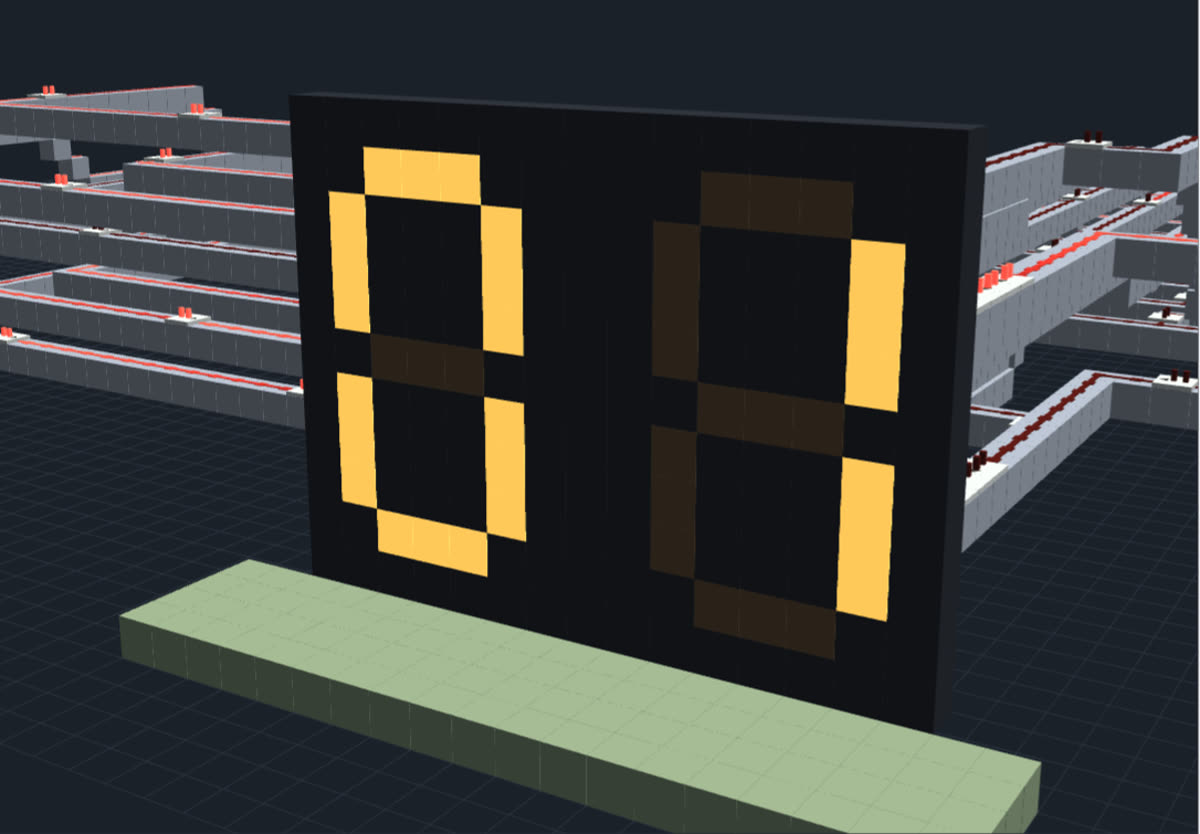
0–9 counter with a wall display
Press the button and the digit counts 0 to 9 and back to 0. Built from repeated modules: a Johnson counter, one decoder slice per pair of cells, and a font table that wires digits to segments.
How it works, part by part
1 · Counter cell 0A master-slave flip-flop (two repeaters that take turns being locked) used as a D flip-flop: on each clock pulse it stores whatever is on its input. Its input is the return wire, NOT Q4, so the five cells form a shift register that a 1 moves along. The five cells go 00000, 10000, 11000 … 11111, 01111 … 00001, then back to 00000: ten states, one per digit.
2 · Counter cell 1A master-slave flip-flop (two repeaters that take turns being locked) used as a D flip-flop: on each clock pulse it stores whatever is on its input. Its input is cell 0's output, so the five cells form a shift register that a 1 moves along. The five cells go 00000, 10000, 11000 … 11111, 01111 … 00001, then back to 00000: ten states, one per digit.
3 · Counter cell 2A master-slave flip-flop (two repeaters that take turns being locked) used as a D flip-flop: on each clock pulse it stores whatever is on its input. Its input is cell 1's output, so the five cells form a shift register that a 1 moves along. The five cells go 00000, 10000, 11000 … 11111, 01111 … 00001, then back to 00000: ten states, one per digit.
4 · Counter cell 3A master-slave flip-flop (two repeaters that take turns being locked) used as a D flip-flop: on each clock pulse it stores whatever is on its input. Its input is cell 2's output, so the five cells form a shift register that a 1 moves along. The five cells go 00000, 10000, 11000 … 11111, 01111 … 00001, then back to 00000: ten states, one per digit.
5 · Counter cell 4A master-slave flip-flop (two repeaters that take turns being locked) used as a D flip-flop: on each clock pulse it stores whatever is on its input. Its input is cell 3's output, so the five cells form a shift register that a 1 moves along. The five cells go 00000, 10000, 11000 … 11111, 01111 … 00001, then back to 00000: ten states, one per digit.
6 · Clock busCarries each press's short pulse to all five cells at once, over a little bridge across the return wire. Repeaters keep it strong along the row.
7 · Return wire (the twist)A torch on the last cell gives NOT Q4, and this wire carries it all the way back to cell 0's input. Feeding back the inverted last bit is what makes a Johnson counter: five cells count ten steps. The wire also feeds the wrap decoder slice.
8 · Decoder for 1 and 6Reads Q0 (L) and Q1 (R). The upper gate is L and not R, digit 1; the lower gate is R and not L, digit 6. Each gate is a comparator in subtract mode with both inputs squared up to 15 by repeaters: 15 - 15 = 0, 15 - 0 = 15. In the Johnson sequence exactly one gate in the whole decoder is on at a time. The repeater delays make each gate turn a digit on 4 ticks after the old one starts turning off, the time a lamp takes to go dark, so the display changes in one step.
9 · Decoder for 2 and 7Reads Q1 (L) and Q2 (R). The upper gate is L and not R, digit 2; the lower gate is R and not L, digit 7. Each gate is a comparator in subtract mode with both inputs squared up to 15 by repeaters: 15 - 15 = 0, 15 - 0 = 15. In the Johnson sequence exactly one gate in the whole decoder is on at a time. The repeater delays make each gate turn a digit on 4 ticks after the old one starts turning off, the time a lamp takes to go dark, so the display changes in one step.
10 · Decoder for 3 and 8Reads Q2 (L) and Q3 (R). The upper gate is L and not R, digit 3; the lower gate is R and not L, digit 8. Each gate is a comparator in subtract mode with both inputs squared up to 15 by repeaters: 15 - 15 = 0, 15 - 0 = 15. In the Johnson sequence exactly one gate in the whole decoder is on at a time. The repeater delays make each gate turn a digit on 4 ticks after the old one starts turning off, the time a lamp takes to go dark, so the display changes in one step.
11 · Decoder for 4 and 9Reads Q3 (L) and Q4 (R). The upper gate is L and not R, digit 4; the lower gate is R and not L, digit 9. Each gate is a comparator in subtract mode with both inputs squared up to 15 by repeaters: 15 - 15 = 0, 15 - 0 = 15. In the Johnson sequence exactly one gate in the whole decoder is on at a time. The repeater delays make each gate turn a digit on 4 ticks after the old one starts turning off, the time a lamp takes to go dark, so the display changes in one step. This slice's R wire has a delay line, so it keeps pace with the long return wire.
12 · Decoder for 0 and 5Reads NOT Q4 (the return wire) (L) and Q0 (R). The upper gate is L and not R, digit 0; the lower gate is R and not L, digit 5. Each gate is a comparator in subtract mode with both inputs squared up to 15 by repeaters: 15 - 15 = 0, 15 - 0 = 15. In the Johnson sequence exactly one gate in the whole decoder is on at a time. The repeater delays make each gate turn a digit on 4 ticks after the old one starts turning off, the time a lamp takes to go dark, so the display changes in one step.
13 · Digit 0 wireOn only while the counter is at 0. It runs south under the ROM and joins the rows of the segments that make a 0: a, b, c, d, e and f.
14 · Digit 1 wireOn only while the counter is at 1. It runs south under the ROM and joins the rows of the segments that make a 1: b and c.
15 · Digit 2 wireOn only while the counter is at 2. It runs south under the ROM and joins the rows of the segments that make a 2: a, b, d, e and g.
16 · Digit 3 wireOn only while the counter is at 3. It runs south under the ROM and joins the rows of the segments that make a 3: a, b, c, d and g.
17 · Digit 4 wireOn only while the counter is at 4. It runs south under the ROM and joins the rows of the segments that make a 4: b, c, f and g.
18 · Digit 5 wireOn only while the counter is at 5. It runs south under the ROM and joins the rows of the segments that make a 5: a, c, d, f and g.
19 · Digit 6 wireOn only while the counter is at 6. It runs south under the ROM and joins the rows of the segments that make a 6: a, c, d, e, f and g.
20 · Digit 7 wireOn only while the counter is at 7. It runs south under the ROM and joins the rows of the segments that make a 7: a, b and c.
21 · Digit 8 wireOn only while the counter is at 8. It runs south under the ROM and joins the rows of the segments that make a 8: a, b, c, d, e, f and g.
22 · Digit 9 wireOn only while the counter is at 9. It runs south under the ROM and joins the rows of the segments that make a 9: a, b, c, d, f and g.
23 · ROM row for segment aSegment a (top) is lit for 0, 2, 3, 5, 6, 7, 8 and 9. Each of those digit wires joins this row through a repeater and a small step up: the repeater only lets signal go one way, so one digit can't leak into another. The repeaters' delays are trimmed so every digit's signal reaches the display at the same moment.
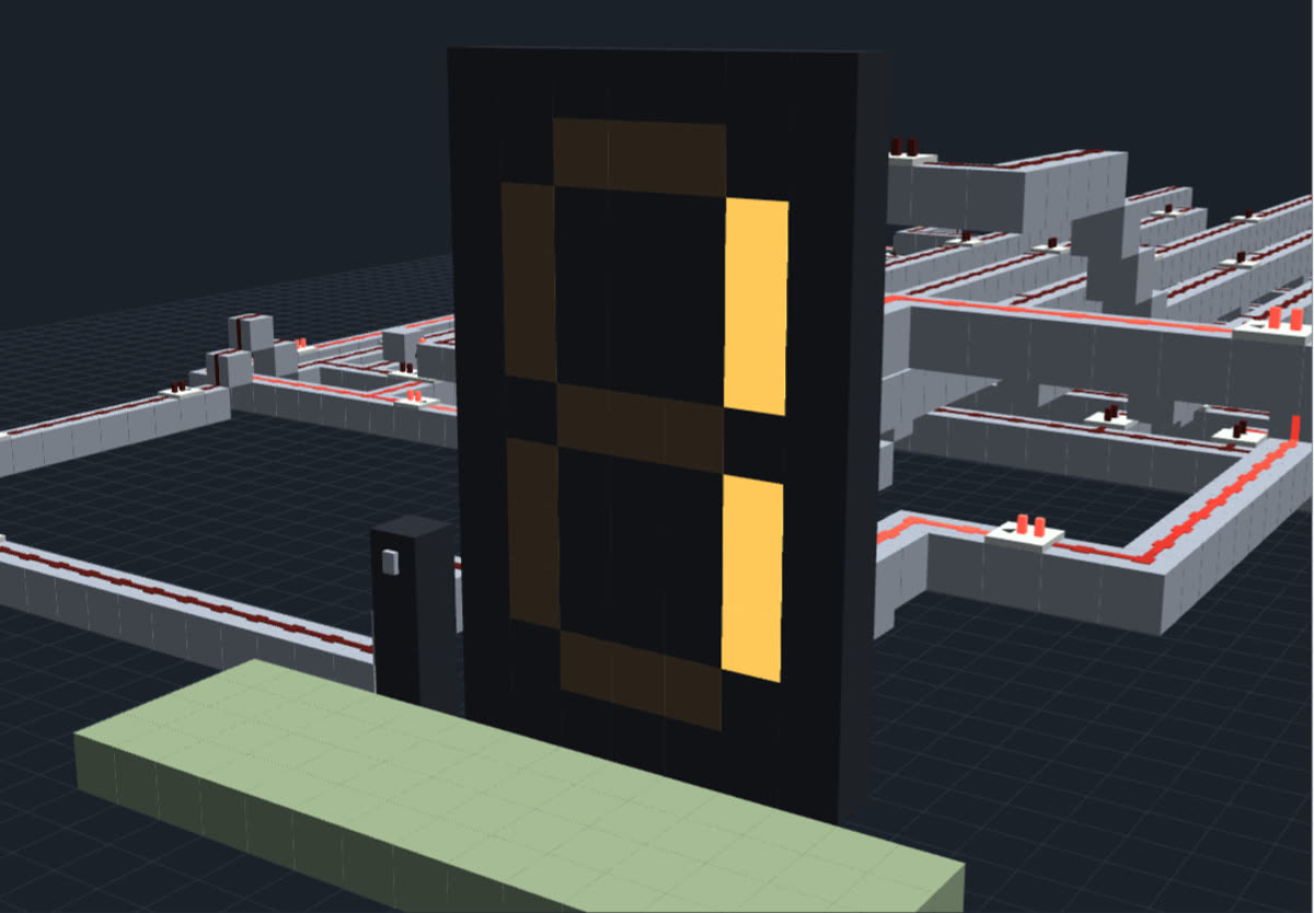
24 · Segment a wireClimbs from the ROM to the height of segment a on the wall and runs to the display. The last repeater powers the middle lamp of the segment; its delay is trimmed so all seven segments switch together.
25 · ROM row for segment bSegment b (top right) is lit for 0, 1, 2, 3, 4, 7, 8 and 9. Each of those digit wires joins this row through a repeater and a small step up: the repeater only lets signal go one way, so one digit can't leak into another. The repeaters' delays are trimmed so every digit's signal reaches the display at the same moment.
26 · Segment b wireClimbs from the ROM to the height of segment b on the wall and runs to the display. The last repeater powers the middle lamp of the segment; its delay is trimmed so all seven segments switch together.
27 · ROM row for segment cSegment c (bottom right) is lit for 0, 1, 3, 4, 5, 6, 7, 8 and 9. Each of those digit wires joins this row through a repeater and a small step up: the repeater only lets signal go one way, so one digit can't leak into another. The repeaters' delays are trimmed so every digit's signal reaches the display at the same moment.
28 · Segment c wireClimbs from the ROM to the height of segment c on the wall and runs to the display. The last repeater powers the middle lamp of the segment; its delay is trimmed so all seven segments switch together.
29 · ROM row for segment dSegment d (bottom) is lit for 0, 2, 3, 5, 6, 8 and 9. Each of those digit wires joins this row through a repeater and a small step up: the repeater only lets signal go one way, so one digit can't leak into another. The repeaters' delays are trimmed so every digit's signal reaches the display at the same moment.
30 · Segment d wireClimbs from the ROM to the height of segment d on the wall and runs to the display. The last repeater powers the middle lamp of the segment; its delay is trimmed so all seven segments switch together.
31 · ROM row for segment eSegment e (bottom left) is lit for 0, 2, 6 and 8. Each of those digit wires joins this row through a repeater and a small step up: the repeater only lets signal go one way, so one digit can't leak into another. The repeaters' delays are trimmed so every digit's signal reaches the display at the same moment.
32 · Segment e wireClimbs from the ROM to the height of segment e on the wall and runs to the display. The last repeater powers the middle lamp of the segment; its delay is trimmed so all seven segments switch together.
33 · ROM row for segment fSegment f (top left) is lit for 0, 4, 5, 6, 8 and 9. Each of those digit wires joins this row through a repeater and a small step up: the repeater only lets signal go one way, so one digit can't leak into another. The repeaters' delays are trimmed so every digit's signal reaches the display at the same moment.
34 · Segment f wireClimbs from the ROM to the height of segment f on the wall and runs to the display. The last repeater powers the middle lamp of the segment; its delay is trimmed so all seven segments switch together.
35 · ROM row for segment gSegment g (middle) is lit for 2, 3, 4, 5, 6, 8 and 9. Each of those digit wires joins this row through a repeater and a small step up: the repeater only lets signal go one way, so one digit can't leak into another. The repeaters' delays are trimmed so every digit's signal reaches the display at the same moment.
36 · Segment g wireClimbs from the ROM to the height of segment g on the wall and runs to the display. The last repeater powers the middle lamp of the segment; its delay is trimmed so all seven segments switch together.
37 · Wall displayA 5 × 9 lamp digit. Each segment is three lamps; the repeater behind the middle lamp powers it, and a powered lamp lights the lamps next to it, because lamps conduct like solid blocks.
38 · ButtonA stone button on a post stays pressed for 1 second (20 ticks). Its wire runs north along the floor to the edge detector.
39 · Rising-edge detectorA comparator in subtract mode reads the button signal at its back and a copy delayed by a repeater at its side, so it only outputs in the 4 ticks between the two arriving. Every press becomes one short clock pulse, however long the button is held.
40 · FloorSomewhere to stand in front of the display.
Build it
Materials
- 1,324× stone
- 1,026× redstone dust
- 161× repeater
- 21× redstone lamp
- 11× comparator
- 6× redstone torch
- 1× button
A build guide and schematic downloads are coming. For now, turn the 3D view and click any block to see what it is.
Want a variant? Ask your AI.
Show me the 0–9 wall counter from Contraptify and make a variant of it. How to connect your AI